
Page 72 - Plastics Engineering
P. 72
Mechanical Behaviour of Plastics 55
Also, the classical elastic equation for the end deflection of a cantilever is:
WL3
deflection, 6 = - (2.12)
3EI
Combining (2.11) and (2.12) gives
36d
strain, E = - (2.13)
2L2
so
2(40)* x 0.005
d= = 2.7 mm
3x2
(ii) The short-term stress in the material is obtained from the short-term modulus
which is given in this question (or could be obtained from the creep/isometric
curves, i.e. at 10 seconds, E = 8 x 10⁶/0.5% = 1.6 GN/m2 or from the appro-
priate isometric curve).
stress = EE = 1.6 x lo9 x 0.005 = 8 MN/m2
(iii) After 1 week (6.1 x lo5 seconds), the isometric curves (Fig. 2.8) derived
from the creep curves show that at a strain of 0.5% the stress would have
decayed to about 3.3 MN/m2.
Example 2.2 A polypropylene beam is 100 mm long, simply supported at
each end and is subjected to a load W at its mid-span. If the maximum permis-
sible strain in the material is to be 1.5%, calculate the largest load which may
be applied so that the deflection of the beam does not exceed 5 mm in a service
life of 1 year. For the beam I = 28 mm4 and the creep curves in Fig. 2.5 should
be used.
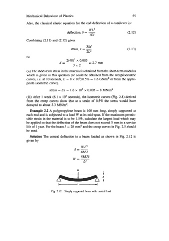
Solution The central deflection in a beam loaded as shown in Fig. 2.12 is
given by
a=- WL3
48EI
48EI6
w=-
L3
W
Fig. 2.12 Simply supported beam with central load