
Page 71 - Plastics Engineering
P. 71
54 Mechanical Behaviour of Plastics
examples. When using this pseudo-elastic design approach it should be remem-
bered that the creep curves used to derive modulus values have normally been
obtained on test pieces which are essentially isotropic. In practice the manu-
facture of the end-product by injection moulding or extrusion, etc. will have
resulted in some degree of anisotropy. This may make the predictions inaccu-
rate because the creep data for the material is no longer appropriate for the
structural morphology introduced by the moulding method. Similar comments
could, of course, also be made about metals in that the test data may have
been obtained on specimens of the material which do not accurately reflect the
nature of the material in the end-product. Therefore, pseudo-elastic design is a
valid analytical procedure but one should always be cautious about the way in
which the manufacturing method has affected the behaviour of the material.
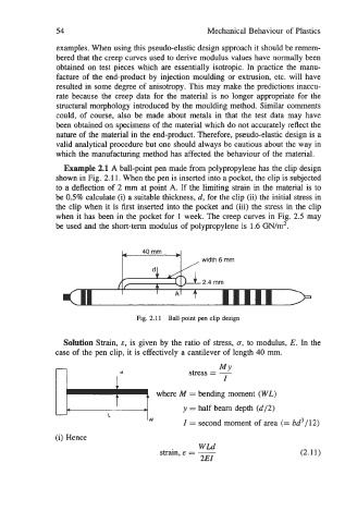
Example 2.1 A ball-point pen made from polypropylene has the clip design
shown in Fig. 2.1 1. When the pen is inserted into a pocket, the clip is subjected
to a deflection of 2 mm at point A. If the limiting strain in the material is to
be 0.5% calculate (i) a suitable thickness, d, for the clip (ii) the initial stress in
the clip when it is first inserted into the pocket and (iii) the stress in the clip
when it has been in the pocket for 1 week. The creep curves in Fig. 2.5 may
be used and the short-term modulus of polypropylene is 1.6 GN/m2.
?--+I , mm
6
width
Fig. 2.1 1 Ball-point pen clip design
Solution Strain, E, is given by the ratio of stress, u, to modulus, E. In the
case of the pen clip, it is effectively a cantilever of length 40 mm.
bw
MY
stress = -
I
where M = bending moment (WL)
y = half beam depth (d/2)
(i) Hence I = second moment of area (= bd3/12)
WLd
strain, E = - (2.11)
2EI