
Page 406 - Polymer-based Nanocomposites for Energy and Environmental Applications
P. 406
Polymer nanocomposites for dye-sensitized solar cells 363
photoelectron generation. The mesoporous structure of metal oxide layer provides
high surface area to maximize the dye intake. A liquid electrolyte, for example, tri-
iodide/iodide redox couple as charge mediator, is introduced between the photoanode
and the CE in order to carry out the regeneration of dye molecules. The CE (cathode) is
usually platinized conductive glass and responsible for catalytic reaction between the
charge from external circuit and the mediator in the electrolyte [7,9].
13.2.1 Energy harvesting mechanism of DSCs
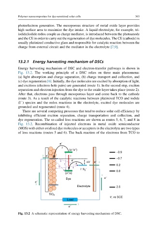
Energy harvesting mechanism of DSC and electron-transfer pathways is shown in
Fig. 13.2. The working principle of a DSC relies on three main phenomena:
(a) light absorption and charge separation, (b) charge transport and collection, and
(c) dye regeneration [6]. Initially, the dye molecules are excited by absorption of light,
and excitons (electron-hole pairs) are generated (route 1). In the second step, exciton
separation and electron injection from the dye to the oxide layer takes place (route 2).
After that, electrons pass through mesoporous layer and come back to the cathode
(route 3). As a result of the catalytic reactions between platinized TCO and iodide
(I ) species and the redox reactions in the electrolyte, excited dye molecules are
grounded and regenerated (route 4).
There are several competing processes that tend to reduce solar cell efficiency by
inhibiting efficient exciton separation, charge transportation and collection, and
dye regeneration. The so-called loss reactions are shown as routes 5, 6, 7, and 8 in
Fig. 13.2. Recombination of injected electrons in metal oxide semiconductor
(MOS) with either oxidized dye molecules or acceptors in the electrolyte are two types
of loss reactions (routes 5 and 6). The back reaction of the electrons from TCO to
e −
2 − +
(s /s )
−0.9
3 e − 1
6 e − ΔV e − −0.7
4 3
7 0.2
5
8 − −
I /I 3 0.8
+
(s /s)
3
e −
Dye
e −
3
Electrolyte 2.5
TiO 2
V, vs SCE
Load
e − 3
Fig. 13.2 A schematic representation of energy harvesting mechanism of DSC.