
Page 266 - Power Electronic Control in Electrical Systems
P. 266
//SYS21/F:/PEC/REVISES_10-11-01/075065126-CH006.3D ± 254 ± [177±262/86] 17.11.2001 10:23AM
254 Power electronic equipment
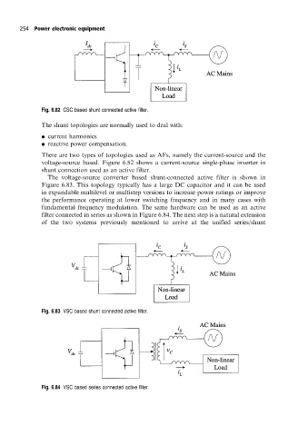
Fig. 6.82 CSC based shunt connected active filter.
The shunt topologies are normally used to deal with:
. current harmonics
. reactive power compensation.
There are two types of topologies used as AFs, namely the current-source and the
voltage-source based. Figure 6.82 shows a current-source single-phase inverter in
shunt connection used as an active filter.
The voltage-source converter based shunt-connected active filter is shown in
Figure 6.83. This topology typically has a large DC capacitor and it can be used
in expandable multilevel or multistep versions to increase power ratings or improve
the performance operating at lower switching frequency and in many cases with
fundamental frequency modulation. The same hardware can be used as an active
filter connected in series as shown in Figure 6.84. The next step is a natural extension
of the two systems previously mentioned to arrive at the unified series/shunt
Fig. 6.83 VSC based shunt connected active filter.
Fig. 6.84 VSC based series connected active filter.