
Page 261 - Power Electronic Control in Electrical Systems
P. 261
//SYS21/F:/PEC/REVISES_10-11-01/075065126-CH006.3D ± 249 ± [177±262/86] 17.11.2001 10:23AM
Power electronic control in electrical systems 249
6.7.2 Advanced concepts in conventional HVDC applications
Although thyristor-based HVDC systems represent mature technology, there are still
exciting developments worth mentioning such as (Arrillaga, 1998):
. active AC and DC filtering (Figure 6.79)
. capacitor commutated converter (CCC) based systems
. air-insulated outdoor thyristor valves
. new and advanced cabling technology
. direct connection of generators to HVDC converters.
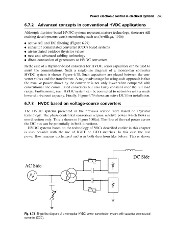
In the case of a thyristor-based converter for HVDC, series capacitors can be used to
assist the commutations. Such a single-line diagram of a monopolar converter
HVDC system is shown Figure 6.78. Such capacitors are placed between the con-
verter valves and the transformer. A major advantage for using such approach is that
the reactive power drawn by the converter is not only lower when compared with
conventional line commutated converters but also fairly constant over the full load
range. Furthermore, such HVDC system can be connected to networks with a much
lower short-circuit capacity. Finally, Figure 6.79 shows an active DC filter installation.
6.7.3HVDC based on voltage-source converters
The HVDC systems presented in the previous section were based on thyristor
technology. The phase-controlled converters require reactive power which flows in
one direction only. This is shown in Figure 6.80(a). The flow of the real power across
the DC bus can be potentially in both directions.
HVDC systems based on the technology of VSCs described earlier in this chapter
is also possible with the use of IGBT or GTO switches. In this case the real
power flow remains unchanged and is in both directions like before. This is shown
Fig. 6.78 Single-line diagram of a monopolar HVDC power transmission system with capacitor commutated
converter (CCC).