
Page 262 - Power Electronic Control in Electrical Systems
P. 262
//SYS21/F:/PEC/REVISES_10-11-01/075065126-CH006.3D ± 250 ± [177±262/86] 17.11.2001 10:23AM
250 Power electronic equipment
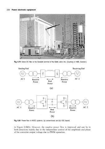
Fig. 6.79 Active DC filter at the Swedish terminal of the Baltic cable link. (Courtesy of ABB, Sweden.)
Fig. 6.80 Power flow in HVDC systems. (a) conventional; and (b) VSC based.
in Figure 6.80(b). However, the reactive power flow is improved and can be in
both directions mainly due to the independent control of the amplitude and phase
of the converter output voltage due to PWM operation.