
Page 257 - Power Electronic Control in Electrical Systems
P. 257
//SYS21/F:/PEC/REVISES_10-11-01/075065126-CH006.3D ± 245 ± [177±262/86] 17.11.2001 10:23AM
Power electronic control in electrical systems 245
Fig. 6.71 Back-to-back HVDC power system with 12-pulse converters.
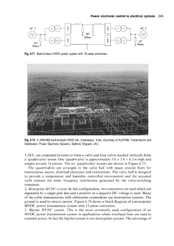
Fig. 6.72 A 1000 MW back-to-back HVDC link, Chandrapur, India. (Courtesy of ALSTOM, Transmission and
Distribution, Power Electronic Systems, Stafford, England, UK.)
5.2 kV, are connected in series to form a valve and four valves stacked vertically form
a `quadrivalve' tower. One `quadrivalve' is approximately 3:8 3:8 6:2 m high and
weighs around 14 tonnes. The six `quadrivalve' towers are shown in Figure 6.73.
The quadrivalves are arranged in the valve hall with space around them for
maintenance access, electrical clearance and connections. The valve hall is designed
to provide a temperature and humidity controlled environment and the screened
walls contain the radio frequency interference generated by the valve-switching
transients.
2. Monopolar HVDC system. In this configuration, two converters are used which are
separated by a single pole line and a positive or a negative DC voltage is used. Many
of the cable transmissions with submarine connections use monopolar systems. The
ground is used to return current. Figure 6.74 shows a block diagram of a monopolar
HVDC power transmission system with 12-pulse converters.
3. Bipolar HVDC system. This is the most commonly used configuration of an
HVDC power transmission system in applications where overhead lines are used to
transmit power. In fact the bipolar system is two monopolar systems. The advantage of