
Page 255 - Power Electronic Control in Electrical Systems
P. 255
//SYS21/F:/PEC/REVISES_10-11-01/075065126-CH006.3D ± 243 ± [177±262/86] 17.11.2001 10:23AM
Power electronic control in electrical systems 243
Fig. 6.68 Circuit configuration of a 12-pulse thyristor converter.
instance DC voltage levels as high as 600 kV have been used in projects and taking
into account that the thyristor blocking voltage is approximately today 8 kV, one can
clearly see that a number of them must be used in series to achieve the required
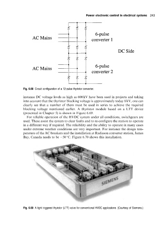
blocking voltage mentioned earlier. A thyristor module based on a LTT device
(presented in Chapter 5) is shown in Figure 6.69.
For reliable operation of the HVDC system under all conditions, switchgears are
used. These assist the system to clear faults and to re-configure the station to operate
in a different way if required. The reliability and the ability to operate in many cases
under extreme weather conditions are very important. For instance the design tem-
perature of the AC breakers and the installation at Radisson converter station, James
Bay, Canada needs to be 50 C. Figure 6.70 shows this installation.
Fig. 6.69 A light triggered thyristor (LTT) valve for conventional HVDC applications. (Courtesy of Siemens.)