
Page 259 - Power Electronic Control in Electrical Systems
P. 259
//SYS21/F:/PEC/REVISES_10-11-01/075065126-CH006.3D ± 247 ± [177±262/86] 17.11.2001 10:23AM
Power electronic control in electrical systems 247
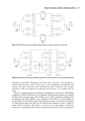
Fig. 6.75 Bipolar HVDC power transmission system based on 12-pulse converter for each pole.
Fig. 6.76 Multi-terminal HVDC power transmission system with 12-pulse converter for each pole parallel connected.
operates as an inverter. Working in the other order, converter 2 can operate as a
rectifier and converters 1 and 3 as an inverter. By mechanically switching the con-
nections of a given converter other combinations can be achieved. For example,
converters 2 and 3 can operate as an inverter and converter 1 as a rectifier and vice
versa.
There is a breakeven point for which the transmission of bulk power with HVDC
as opposed to HVAC becomes more economical. Although the projects are evaluated
on their own economic terms and conditions, it is widely accepted by industry that
the distance that makes HVDC more competitive than HVAC is about 800 km or
greater in the case of overhead lines. This distance becomes a lot shorter if submarine
or underground cables are used for the transmission bringing it down to approxi-
mately 50 km or greater. This allows of course not only the trading of electricity
between two networks but also economic exploitation of remote site power generation.