
Page 254 - Power Electronic Control in Electrical Systems
P. 254
//SYS21/F:/PEC/REVISES_10-11-01/075065126-CH006.3D ± 242 ± [177±262/86] 17.11.2001 10:23AM
242 Power electronic equipment
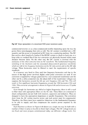
Fig. 6.67 Simple representation of a conventional HVDC power transmission system.
commutated inverter or as a line-commutated rectifier depending upon the way the
power flows interchanging their role as well. The AC current is rectified into a DC
quantity and the power is transmitted in DC form via a conducting medium. The DC
line can be a short length of a busbar if the HVDC system is a back-to-back one, or a
long cable or overhead line if the two converters are physically located within some
distance between them. On the other end, the DC current is inverted with the
assistance of the other converter into an AC waveform. The fundamental frequency
switching of the thyristors and the associated phase-control generates waveforms
which are rich in low frequency harmonics on the AC side current and on the DC side
voltage. These harmonics must be filtered to meet the requirements of specific
standards.
It is however very hard to filter such low frequency harmonics and due to the
nature of the high power involved, higher order pulse converters are used. If one
converter is supplied by voltages generated by a star-connected transformer and the
other one by a delta-connected one, the phase-shift of the transformer voltages can
suppress the harmonics around the 6th per unit frequency (5th and 7th). This will
result in first significant harmonic frequencies around the 12th harmonic (11th and
13th). This converter arrangement is shown in Figure 6.68 and is known as a 12-pulse
converter.
Even though the harmonics are shifted at higher frequencies, there is still a need
to filter them with appropriate filters on the AC side. These filters are connected in
shunt configuration and are built with resistors, capacitors and inductors. They are
designed to have the appropriate impedance at specific frequencies. The converters
draw from the AC system reactive power and such power must be compensated.
Therefore, the filters must have capacitive behaviour at the fundamental frequency
to be able to supply and thus compensate the reactive power required by the
converter.
Each thyristor as shown in Figure 6.68 drawn as a single one may be built with a
number of them in series to be able to block high voltages. The DC voltage levels are
not fixed and most projects commissioned today use different voltage levels. For