
Page 256 - Power Electronic Control in Electrical Systems
P. 256
//SYS21/F:/PEC/REVISES_10-11-01/075065126-CH006.3D ± 244 ± [177±262/86] 17.11.2001 10:23AM
244 Power electronic equipment
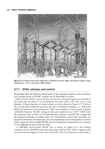
Fig. 6.70 AC breakers and current transformers at Radisson converter station, James Bay, Canada. Design
temperature is 50 C. (Courtesy of ABB, Sweden.)
6.7.1 HVDC schemes and control
Depending upon the function and location of the converter stations, various schemes
and configurations of HVDC systems can be identified as follows:
1. Back-to-back HVDC system. In this case the two converter stations are located at
the same site and there is no transmission of power with a DC link over a long
distance. A block diagram of a back-to-back system is shown in Figure 6.71. The two
AC systems interconnected may have the same or different frequency, i.e. 50 Hz and
60 Hz (asynchronous interconnection). There are examples of such systems in Japan
and South America. The DC voltage in this case is quite low (i.e. 50 kV±150 kV) and
the converter does not have to be optimized with respect to the DC bus voltage and
the associated distance to reduce costs, etc. Furthermore, since both converters are
physically located in the same area, the civil engineering costs of the project are lower
when compared with a similar HVDC power transmission system where two stations
at two different locations must be built.
A 1000 MW back-to-back HVDC link is shown in Figure 6.72. The scheme
comprises of two 500 MW poles each operating at 205 kV DC, 2474 A together with
conventional switchgears at each end of the link. Fifty-four thyristors, each rated at