
Page 258 - Power Electronic Control in Electrical Systems
P. 258
//SYS21/F:/PEC/REVISES_10-11-01/075065126-CH006.3D ± 246 ± [177±262/86] 17.11.2001 10:23AM
246 Power electronic equipment
Fig. 6.73 Inside the valve hall, showing its six `quadrivalve' towers. (Courtesy of ALSTOM, Transmission and
Distribution, Power Electronic Systems, Stafford, England, UK.)
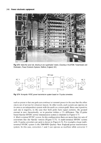
Fig. 6.74 Monopolar HVDC power transmission system based on 12-pulse converters.
such a system is that one pole can continue to transmit power in the case that the other
one is out of service for whatever reason. In other words, each system can operate on
its own as an independent system with the earth as a return path. Since one is positive
and one is negative, in the case that both poles have equal currents, the ground
current is zero theoretically, or in practice within a 1% difference. The 12-pulse
based bipolar HVDC power transmission system is depicted in Figure 6.75.
4. Multi-terminal HVDC system. In this configuration there are more than two sets of
converters like the bipolar version (Figure 6.75). A multi-terminal HVDC system
with 12-pulse converters per pole is shown in Figure 6.76. For example a large multi-
terminal HVDC system is the 2000 MW Quebec±New England power transmission
system. In this case, converters 1 and 3 can operate as rectifiers while converter 2