
Page 264 - Power Electronic Control in Electrical Systems
P. 264
//SYS21/F:/PEC/REVISES_10-11-01/075065126-CH006.3D ± 252 ± [177±262/86] 17.11.2001 10:23AM
252 Power electronic equipment
È
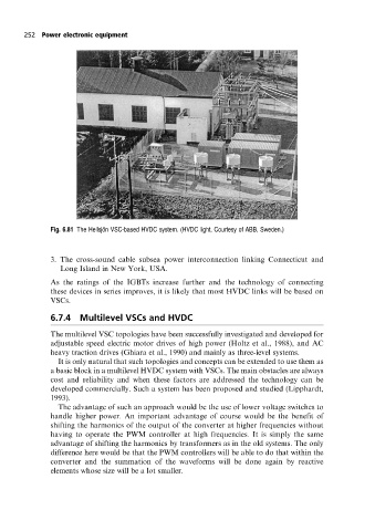
Fig. 6.81 The Hellsjon VSC-based HVDC system. (HVDC light, Courtesy of ABB, Sweden.)
3. The cross-sound cable subsea power interconnection linking Connecticut and
Long Island in New York, USA.
As the ratings of the IGBTs increase further and the technology of connecting
these devices in series improves, it is likely that most HVDC links will be based on
VSCs.
6.7.4 Multilevel VSCs and HVDC
The multilevel VSC topologies have been successfully investigated and developed for
adjustable speed electric motor drives of high power (Holtz et al., 1988), and AC
heavy traction drives (Ghiara et al., 1990) and mainly as three-level systems.
It is only natural that such topologies and concepts can be extended to use them as
a basic block in a multilevel HVDC system with VSCs. The main obstacles are always
cost and reliability and when these factors are addressed the technology can be
developed commercially. Such a system has been proposed and studied (Lipphardt,
1993).
The advantage of such an approach would be the use of lower voltage switches to
handle higher power. An important advantage of course would be the benefit of
shifting the harmonics of the output of the converter at higher frequencies without
having to operate the PWM controller at high frequencies. It is simply the same
advantage of shifting the harmonics by transformers as in the old systems. The only
difference here would be that the PWM controllers will be able to do that within the
converter and the summation of the waveforms will be done again by reactive
elements whose size will be a lot smaller.