
Page 278 - Power Electronic Control in Electrical Systems
P. 278
//SYS21/F:/PEC/REVISES_10-11-01/075065126-CH007.3D ± 266 ± [263±289/27] 17.11.2001 10:24AM
266 Harmonic studies of power compensating plant
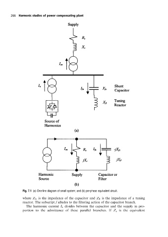
Fig. 7.1 (a) One-line diagram of small system; and (b) per-phase equivalent circuit.
where Z fc is the impedance of the capacitor and Z fl is the impedance of a tuning
reactor. The subscript f alludes to the filtering action of the capacitor branch.
The harmonic current I n divides between the capacitor and the supply in pro-
portion to the admittance of these parallel branches. If Z s is the equivalent