
Page 283 - Power Electronic Control in Electrical Systems
P. 283
//SYS21/F:/PEC/REVISES_10-11-01/075065126-CH007.3D ± 271 ± [263±289/27] 17.11.2001 10:24AM
Power electronic control in electrical systems 271
0
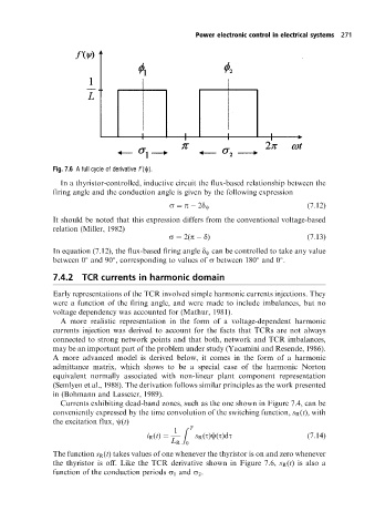
Fig. 7.6 Afull cycle of derivative f (c).
In a thyristor-controlled, inductive circuit the flux-based relationship between the
firing angle and the conduction angle is given by the following expression
s p 2d c (7:12)
It should be noted that this expression differs from the conventional voltage-based
relation (Miller, 1982)
s 2(p d) (7:13)
In equation (7.12), the flux-based firing angle d c can be controlled to take any value
between 0 and 90 , corresponding to values of s between 180 and 0 .
7.4.2 TCR currents in harmonic domain
Early representations of the TCR involved simple harmonic currents injections. They
were a function of the firing angle, and were made to include imbalances, but no
voltage dependency was accounted for (Mathur, 1981).
A more realistic representation in the form of a voltage-dependent harmonic
currents injection was derived to account for the facts that TCRs are not always
connected to strong network points and that both, network and TCR imbalances,
may be an important part of the problem under study (Yacamini and Resende, 1986).
A more advanced model is derived below, it comes in the form of a harmonic
admittance matrix, which shows to be a special case of the harmonic Norton
equivalent normally associated with non-linear plant component representation
(Semlyen et al., 1988). The derivation follows similar principles as the work presented
in (Bohmann and Lasseter, 1989).
Currents exhibiting dead-band zones, such as the one shown in Figure 7.4, can be
conveniently expressed by the time convolution of the switching function, s R (t), with
the excitation flux, c(t)
1 Z T
i R (t) s R (t)c(t)dt (7:14)
L R 0
The function s R (t) takes values of one whenever the thyristor is on and zero whenever
the thyristor is off. Like the TCR derivative shown in Figure 7.6, s R (t) is also a
function of the conduction periods s 1 and s 2 .