
Page 281 - Power Electronic Control in Electrical Systems
P. 281
//SYS21/F:/PEC/REVISES_10-11-01/075065126-CH007.3D ± 269 ± [263±289/27] 17.11.2001 10:24AM
Power electronic control in electrical systems 269
The equation for r becomes
f
R s jX s
r (7:10)
f
R s j(X s X fl X fc )
Figure 7.2(b) shows the response in terms of r and r with the tuning reactor. Note
f
s
that r 1 at the 5th harmonic, i.e. r 0, and is maximum (parallel resonance) at a
f
s
lower harmonic order, about 3.54.
7.4Thyristor-controlled reactors
7.4.1 TCR periodic characteristics
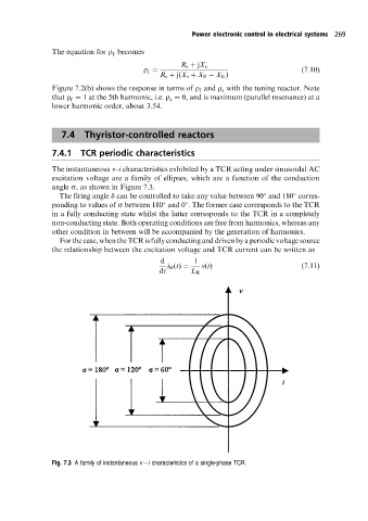
The instantaneous v±i characteristics exhibited by a TCR acting under sinusoidal AC
excitation voltage are a family of ellipses, which are a function of the conduction
angle s, as shown in Figure 7.3.
The firing angle d can be controlled to take any value between 90 and 180 corres-
ponding to values of s between 180 and 0 . The former case corresponds to the TCR
in a fully conducting state whilst the latter corresponds to the TCR in a completely
non-conducting state. Both operating conditions are free from harmonics, whereas any
other condition in between will be accompanied by the generation of harmonics.
For the case, whenthe TCR is fully conducting and driven by a periodic voltage source
the relationship between the excitation voltage and TCR current can be written as
d 1
i R (t) v(t) (7:11)
dt L R
Fig. 7.3 Afamily of instantaneous v i characteristics of a single-phase TCR.