
Page 369 - Power Electronic Control in Electrical Systems
P. 369
//SYS21/F:/PEC/REVISES_10-11-01/075065126-CH008.3D ± 350 ± [290±372/83] 17.11.2001 10:29AM
350 Transient studies of FACTS and Custom Power equipment
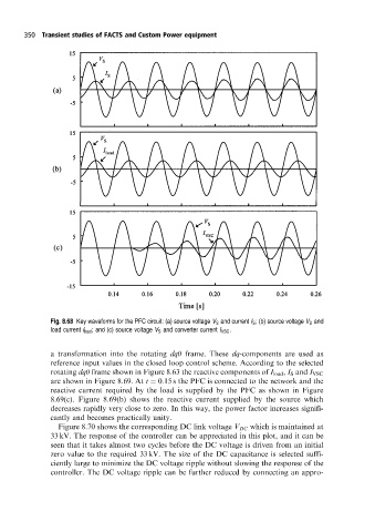
Fig. 8.68 Key waveforms for the PFC circuit: (a) source voltage V S and current I S ; (b) source voltage V S and
load current I load ; and (c) source voltage V S and converter current I VSC .
a transformation into the rotating dq0 frame. These dq-components are used as
reference input values in the closed loop control scheme. According to the selected
rotating dq0 frame shown in Figure 8.63 the reactive components of I load , I S and I VSC
are shown in Figure 8.69. At t 0:15 s the PFC is connected to the network and the
reactive current required by the load is supplied by the PFC as shown in Figure
8.69(c). Figure 8.69(b) shows the reactive current supplied by the source which
decreases rapidly very close to zero. In this way, the power factor increases signifi-
cantly and becomes practically unity.
Figure 8.70 shows the corresponding DC link voltage V DC which is maintained at
33 kV. The response of the controller can be appreciated in this plot, and it can be
seen that it takes almost two cycles before the DC voltage is driven from an initial
zero value to the required 33 kV. The size of the DC capacitance is selected suffi-
ciently large to minimize the DC voltage ripple without slowing the response of the
controller. The DC voltage ripple can be further reduced by connecting an appro-