
Page 371 - Power Electronic Control in Electrical Systems
P. 371
//SYS21/F:/PEC/REVISES_10-11-01/075065126-CH008.3D ± 352 ± [290±372/83] 17.11.2001 10:29AM
352 Transient studies of FACTS and Custom Power equipment
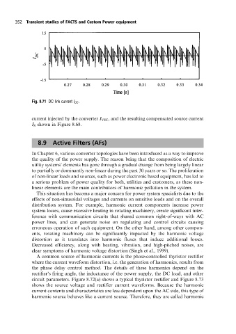
Fig. 8.71 DC link current I DC .
current injected by the converter I VSC , and the resulting compensated source current
I S shown in Figure 8.68.
8.9 Active Filters (AFs)
In Chapter 6, various converter topologies have been introduced as a way to improve
the quality of the power supply. The reason being that the composition of electric
utility systems' elements has gone through a gradual change from being largely linear
to partially or dominantly non-linear during the past 30 years or so. The proliferation
of non-linear loads and sources, such as power electronic based equipment, has led to
a serious problem of power quality for both, utilities and customers, as these non-
linear elements are the main contributors of harmonic pollution in the system.
This situation has become a major concern for power system specialists due to the
effects of non-sinusoidal voltages and currents on sensitive loads and on the overall
distribution system. For example, harmonic current components increase power
system losses, cause excessive heating in rotating machinery, create significant inter-
ference with communication circuits that shared common right-of-ways with AC
power lines, and can generate noise on regulating and control circuits causing
erroneous operation of such equipment. On the other hand, among other compon-
ents, rotating machinery can be significantly impacted by the harmonic voltage
distortion as it translates into harmonic fluxes that induce additional losses.
Decreased efficiency, along with heating, vibration, and high-pitched noises, are
clear symptoms of harmonic voltage distortion (Singh et al., 1999).
A common source of harmonic currents is the phase-controlled thyristor rectifier
where the current waveform distortion, i.e. the generation of harmonics, results from
the phase delay control method. The details of these harmonics depend on the
rectifier's firing angle, the inductance of the power supply, the DC load, and other
circuit parameters. Figure 8.72(a) shows a typical thyristor rectifier and Figure 8.73
shows the source voltage and rectifier current waveforms. Because the harmonic
current contents and characteristics are less dependent upon the AC side, this type of
harmonic source behaves like a current source. Therefore, they are called harmonic