
Page 375 - Power Electronic Control in Electrical Systems
P. 375
//SYS21/F:/PEC/REVISES_10-11-01/075065126-CH008.3D ± 356 ± [290±372/83] 17.11.2001 10:29AM
356 Transient studies of FACTS and Custom Power equipment
8.9.1 Shunt active filter
The topology of a VSC connected in shunt with the AC system was used in previous
sections as a STATCOM and PFC for power factor improvement. This section
presents the time domain analysis of this topology when used as shunt active filter
for the elimination of current harmonics. A simple control scheme is developed to
regulate the operation of the active filter and transient simulations are carried out in
PSCAD/EMTDC.
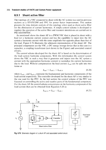
As mentioned above the shunt AF is a PWM VSC that is placed in shunt with a
load (or a harmonic current source) and has the capability to inject into the AC
system a harmonic current with the same amplitude but opposite phase than that of
the load. Figure 8.76 illustrates the schematic representation of the shunt AF. The
principal components are the VSC, a DC energy storage device that in this case is a
capacitor, a coupling transformer (not shown in the Figure) and associated control
circuits.
The control scheme developed for the shunt AF is based on the determination of
the load current harmonic components. With this information the control system
drives the VSC in such a way that it generates and injects into the AC system a
current with the appropriate harmonic content to neutralize the current harmonics
due to the load. Without compensation the load current I load can be split into two
terms as
(8:20)
I load I load 1 I load h
where I load 1 and I load h represent the fundamental and harmonic components of the
load current respectively. The controller developed for the shunt AF is very similar to
the one used for the PFC. In the last section the control scheme of the PFC was
focussed on controlling the active and reactive parts of the fundamental component.
For the shunt AF the control scheme concentrates on the harmonic component of the
load current that can be obtained from Equation 8.20 as
I load h I load I load 1 (8:21)
Fig. 8.76 Schematic diagram ofa shunt AF and associated control circuit.