
Page 370 - Power Electronic Control in Electrical Systems
P. 370
//SYS21/F:/PEC/REVISES_10-11-01/075065126-CH008.3D ± 351 ± [290±372/83] 17.11.2001 10:29AM
Power electronic control in electrical systems 351
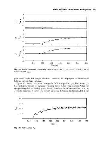
Fig. 8.69 Reactive components in the rotating frame: (a) load current I load d ; (b) source current I S d ; and (c)
converter current I VSC d .
priate filter at the VSC output terminals. However, for the purpose of this example
filtering has not been included.
Figure 8.71 shows the current through the DC link capacitor, I DC . The current I DC
has the typical pattern for the case of lagging power factor compensation. When the
compensation is for a leading power factor the orientation of the waveform is in the
opposite direction. It shows low current harmonic distortion that is reflected in the
Fig. 8.70 DC link voltage V DC .