
Page 418 - Power Electronic Control in Electrical Systems
P. 418
//SYS21/F:/PEC/REVISES_10-11-01/075065126-CH009.3D ± 397 ± [373±406/34] 17.11.2001 10:33AM
Power electronic control in electrical systems 397
With three-wire connection, i a i b i c 0
\ p v a i a v b i b v c (i a i b )
(v a v c )i a (v b v c )i b
v ab i a v bc i b
(iii) (a) I 115/(3 j14) 115/(14:318e j77:905 ) 8:032e j77:905 A
(b) P jQ VI 115 8:032e j77:905 193:537 j903:171 VA
(c) Wattmeter voltage coil reads only 1/4 of the load voltage, so the reading is
W 193:537/4 48:38 W.
(d) Wattmeter voltage coil voltage is
j6:429
115 24:097e j77:904 V
30 j6:429
Wattmeter coil current is 8:032e j77:905 A.
\ Wattmeter reads Re fVI g Ref24:097e j77:904 8:032e j77:905 g
193:55 W
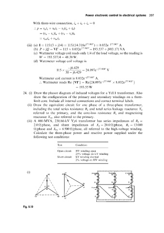
24. (i) Draw the phasor diagram of induced voltages for a Yd11 transformer. Also
draw the configuration of the primary and secondary windings on a three-
limb core. Include all internal connections and correct terminal labels.
(ii) Draw the equivalent circuit for one phase of a three-phase transformer,
including the total series resistance R e and total series leakage reactance X e
referred to the primary, and the core-loss resistance R c and magnetizing
reactance X m , also referred to the primary.
(iii) A 400-MVA, 230/66-kV Yy6 transformer has series impedances of R e
2:0
/phase, and shunt impedances of X e 20:0
/phase, R c 13 000
/phase and X m 6 500
/phase, all referred to the high-voltage winding.
Calculate the three-phase power and reactive power supplied under the
following test conditions:
Test Condition
Open circuit HV winding open
25% voltage on LV winding
Short circuit LV winding shorted
2% voltage on HV winding
(i)
Fig. 9.19