
Page 417 - Power Electronic Control in Electrical Systems
P. 417
//SYS21/F:/PEC/REVISES_10-11-01/075065126-CH009.3D ± 396 ± [373±406/34] 17.11.2001 10:33AM
396 Examples, problems and exercises
Fig. 9.17
p
(b) I a 415/ 3/9:184 26:088 A (unchanged)
p p
I b 415/ 3e j120 /(3 j17 150/50) 415/ 3e j120 /51:088e j86:634
4:690e j206:634 4:192 j2:102 A
p p
I c 415/ 3e j120 /(3 j17 50/150) 415/ 3e j120 /6:412e j62:103
37:369e j182:103 37:344 j1:371 A
I n I a I b I c 15:448 j0:731 15:465e j177:29 A.
23. (i) Draw a circuit diagram and a phasor diagram showing the two-wattmeter
method of measuring power in a three-phase system.
(ii) Prove from first principles that the two-wattmeter method is valid for
instantaneous power and not just for average power.
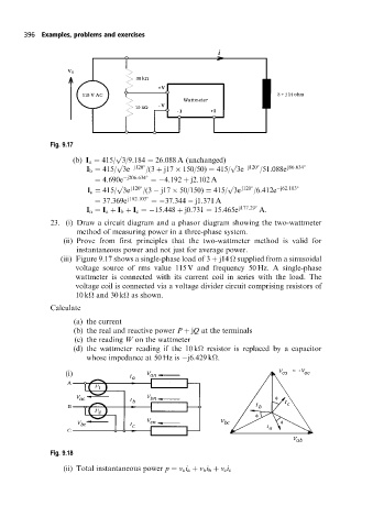
(iii) Figure 9.17 shows a single-phase load of 3 j14
supplied from a sinusoidal
voltage source of rms value 115 V and frequency 50 Hz. A single-phase
wattmeter is connected with its current coil in series with the load. The
voltage coil is connected via a voltage divider circuit comprising resistors of
10 k
and 30 k
as shown.
Calculate
(a) the current
(b) the real and reactive power P jQ at the terminals
(c) the reading W on the wattmeter
(d) the wattmeter reading if the 10 k
resistor is replaced by a capacitor
whose impedance at 50 Hz is j6:429 k
.
(i)
Fig. 9.18
(ii) Total instantaneous power p v a i a v b i b v c i c