Page 414 - Power Electronic Control in Electrical Systems
P. 414

//SYS21/F:/PEC/REVISES_10-11-01/075065126-CH009.3D ± 393 ± [373±406/34] 17.11.2001 10:33AM


                                                            Power electronic control in electrical systems 393
                                        p p         2      p       2   p        2
                         (ii) (a) I L(rms) ˆ  [(3   12:5) ‡ 0 ‡ (3   4:5) ‡ (3   3:0) ]
                                        p
                                      ˆ  [468:75 ‡ 0 ‡ 60:75 ‡ 27:0]
                                      ˆ 23:59A(rms)
                                        p    2      2      2
                             (b) V L(rms) ˆ  [220 ‡ 19:0 ‡ 15:0 ]
                                      ˆ 221:33 V(rms)
                             (c) P ˆ 3   [220   12:5 cos 15:0 ‡ 19:0   4:5cos 21:0

                                    ‡ 15:0   6:0 cos ( 26:0 )]

                                  ˆ 2656:30 ‡ 79:82 ‡ 80:89
                                  ˆ 2817:00 W                       p
                                                                             2
                                                                  2
                             (d) Cable loss ratio ˆ I 2  /I 2  ˆ 23:59 /( 3   12:5) ˆ 1:187
                                                 L(rms)  1(rms)
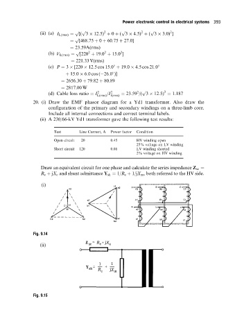
                      20. (i) Draw the EMF phasor diagram for a Yd1 transformer. Also draw the
                             configuration of the primary and secondary windings on a three-limb core.
                             Include all internal connections and correct terminal labels.
                         (ii) A 230/66-kV Yd1 transformer gave the following test results:


                               Test      Line Current, A  Power factor  Condition
                               Open circuit  20        0.45      HV winding open
                                                                 25% voltage on LV winding
                               Short circuit  120      0.08      LV winding shorted
                                                                 2% voltage on HV winding


                         Draw an equivalent circuit for one phase and calculate the series impedance Z se ˆ
                         R e ‡ jX e and shunt admittance Y sh ˆ 1/R c ‡ 1/jX m , both referred to the HV side.

                          (i)


                      Fig. 9.14

                         (ii)


                      Fig. 9.15
   409   410   411   412   413   414   415   416   417   418   419