
Page 412 - Power Electronic Control in Electrical Systems
P. 412
//SYS21/F:/PEC/REVISES_10-11-01/075065126-CH009.3D ± 391 ± [373±406/34] 17.11.2001 10:33AM
Power electronic control in electrical systems 391
(ii)
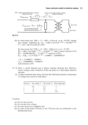
Fig. 9.12
p
(iii) In short-circuit test: 2490 3 1005 14:4cos f,so f 84:299 (current
p
lags voltage). Neglecting Z sh , Z se (1005/ 3)/(14:4e 84:299 ) 40:294e j84:299
4:00 j40:0
(referred to HV).
p
In open-circuit test: 2500 3 400 3:886 cos f,so f 21:786
p
Z (400/ 3)/(3:886e 21:786 ) 59:429e j21:786 ohm ( means referred to LV)
00
00
sh
2
00
Z sh (10 000/400) Z 37 143e j21:786 (referred to HV)
sh
Y sh 1/Z sh (1/37 143)e j21:786 0:000025 j0:00000992 S
\R c 1/0:000025 40 000
;
X m 1/0:00000992 100 000
,
both referred to HV.
19. (i) Draw a circuit diagram and a phasor diagram showing how third-har-
monic voltages cause oscillation of the star point in a three-phase electrical
network.
(ii) A delta-connected three-phase load has the following harmonic components
of voltage and current in each phase:
Harmonic rms voltage, V rms current, A Phase angle (deg.)
1 220 12.5 15
3 0 11.5 ±
5 19 4.5 21
7 15 6 26.0
Calculate
(a) the rms line current;
(b) the rms line±line voltage;
(c) the total mean power supplied; and
2
2
(d) the ratio of the actual I R losses to the I R losses that are attributable to the
fundamental alone.