
Page 410 - Power Electronic Control in Electrical Systems
P. 410
//SYS21/F:/PEC/REVISES_10-11-01/075065126-CH009.3D ± 389 ± [373±406/34] 17.11.2001 10:33AM
Power electronic control in electrical systems 389
(ii) From supply diagram, I L I ph in all three lines/phases. From the voltage
p
diagram, V RY 2cos 30 V RN 3V RN ; other lines/phases likewise.
From load diagram, I R I 1 I 3 and if balanced, I L 2 cos 30
p
I ph 3I ph .
j0
(iii) 6000 j0 V RY I 415e I
RY RY so I RY 14:458A I 1
1
(4500/0:8)e j cos (0:8) 415e j120 I so I YB 13:554e j156:87 A 12:464
YB
j5:324A I 2
1
(2700/0:5)e j cos (0:5) 415e j120 I so I BR 13:012A I 3
BR
I R I 1 I 3 27:470A
I Y I 2 I 1 26:922 j5:324A 27:444e j168:813 A
I B I 3 I 2 0:548 j5:324A 5:352e j95:877 A
Average line current/Average phase current (27:470 27:444 5:352)/
(14:458 13:554 13:012) 1:469.
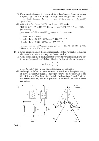
17. (i) Draw a circuit diagram showing the connection of two wattmeters to measure
the power in a three-wire supply to a three-phase load.
(ii) Using a suitable phasor diagram for the two-wattmeter connection, prove that
the power-factor angle f of a balanced load can be determined from the equation
p P 1 P 2
tan f 3
P 1 P 2
where P 1 and P 2 are the readings on the individual wattmeters.
(iii) A three-phase AC motor draws balanced currents from a three-phase supply.
Its power factor is 0.85 lagging. The output power of the motor is 9.7 kW and
the efficiency is 92%. Determine the individual readings P 1 and P 2 of two
wattmeters measuring the input power to the motor in the two-wattmeter
connection.
(i)
Fig. 9.11