
Page 169 - Power Electronics Handbook
P. 169
Phase control 161
time t2 to t21. The load voltage remains at zero until TH2 is fired at time t3.
Clearly if a<+, the load current and voltage will be sinusoidal.
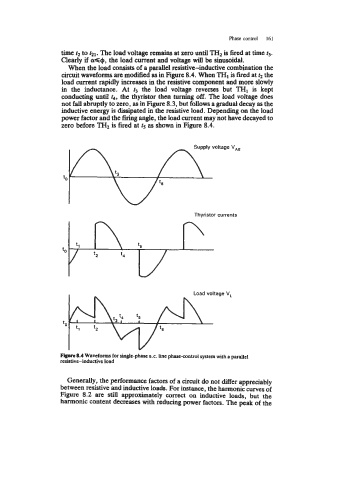
When the load consists of a parallel resistive-inductive combination the
circuit waveforms are modified as in Figure 8.4. When TH1 is fired at t2 the
load current rapidly increases in the resistive component and more slowly
in the inductance. At f3 the load voltage reverses but TH1 is kept
conducting until t4, the thyristor then turning off. The load voltage does
not fall abruptly to zero, as in Figure 8.3, but follows a gradual decay as the
inductive energy is dissipated in the resistive load. Depending on the load
power factor and the firing angle, the load current may not have decayed to
zero before TH2 is fired at t5 as shown in Figure 8.4.
Thyristor currents
Figwe 8.4 Waveforms for single-phase a.c. Line phase-control system with a parallel
resistive-inductive load
Generally, the performance factors of a circuit do not differ appreciably
between resistive and inductive loads. For instance, the harmonic curves of
Figure 8.2 are still approximately correct on inductive loads, but the
harmonic content decreases with reducing power factors. The peak of the