
Page 170 - Power Electronics Handbook
P. 170
162 Static switches
third harmonic will also now shift to slightly higher firing angles. The r.m.s.
thyristor current and load voltage for a series resistance-inductance load
are given by equation (8.4).
v 1 x-a sin (’ - a) COS (a + x + +)}I (8.4)
M
-
ZT(rms) = z [T {y JcCOS+
I”
v, = v x - a - sin (x - a) cos (x + a)
Jc (8.5)
Z is the load impedance and the cut-off angle x, in Figure 8.3, is given by
equation (8.5).
sin (x - +) - sin (a - +) exp {-cot + (x - a)} = o (8.6)
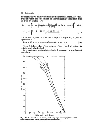
Figure 8.5 shows plots of the variation of the r.m.s. load voltage for
resistive and inductive loads.
As in most power semiconductor circuits, it is necessary to guard against
two effects:
80 -
-
70
a,
m
m
U
m
0
- 50-
4
I
K
a? 40-
30 -
-
20
lot., , I ,
0
0 20 40 60 80 100 120 140 160 1 0
Firing angle I a ) in degrees
Flgare 8.S Variation of r.m.8. load voltage with firing angle, for a single-phase a.c. line
phascantrol system having a series resistive-inductive load