
Page 171 - Power Electronics Handbook
P. 171
Phase control 163
(9 dddt. When the load is capacitive a rapid rise in charging current can
occur on initially turning on the power device. This dYdt effect can
destroy the semiconductors by causing local hot spots, even though
the r.m.s. current rating has not been exceeded. When the load is a
transformer stray capacitance across it would produce the same
effect. In all such cases a linear or saturable reactor, in series with the
power semiconductor, can be used to slow down the rate of current
change.
(ii) dv/dt. Referring to Figure 8.l(a) and Figure 8.3, it can be seen that
"HI conducts from period tl to fzl, the voltage across TH2 being
negligible during this period. At tZ1 thyristor THl goes off and the
voltage across TH2 rises rapidly to the value of the input line voltage
at this point. This dvldt effect can cause the thyristor to switch on and
conduct, even in the absence of a gate signal. The effect is more
pronounced when triacs are used, since the device will have been
conducting in the previous half cycle before it sees the dv/dt rise
during its off period. It can be damped by R-C circuits across the
power semiconductors, which reduce the rate of rise of voltage but
also increase the turn-off time of the components.
R
Y ,61"1
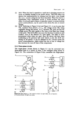
8.2.2 Three-phase circuits
The single-phase circuits shown in Figure 8.1 can be converted into
three-phase lines in a variety of ways, a few examples being shown in
Figure 8.6. The connection of Figure 8.qa) resembles the single-phase
ULoad
00
LC
aS
B 02 -22 LLa
v)O
(4
R
Y
B
B
(a)
(4
Figure 8.6 Three-phase a.c. line control circuits: (a) open delta; (b) six-thyristor;
(c) thyristor/diode; (d) half-wave delta