
Page 218 - Power Electronics Handbook
P. 218
208 Phase-controlled rectification and inversion
completed at tal. As soon as the red phase is released by the yellow phase it
goes into overlap with the blue phase, as current transfers from D1 to D5
and flows to D6. At tl transfer should occur between D6 and D2, but since
the blue phase voltage is held above that of the yellow phase, owing to its
overlap with the red phase, this transfer is delayed until til. This waveform
shows that there has been an artificially created delay angle of about 10" in
the changeover point between phases. Similarly, in Figure 9.31(b) the
increased load current still gives the same value of 60" overlap, but
increases the delay to 30", which represents the boundary condition
between mode-two and mode-three operation. It should be noted that,
throughout mode two, three diodes are conducting at any one time.
Figure 9.32 shows mode-three operation, with overlap angles exceeding
60". The two overlap periods of the top and bottom halves of the bridge
now run into each other so that four devices begin to conduct
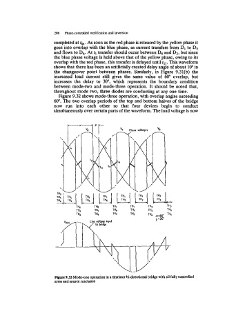
simultaneously over certain parts of the waveform. The load voltage is now
Figure 9.33 Mode-one operation in a thyristor bi-dmctional bridge with all fully controlled
arms and source reactance