
Page 222 - Power Electronics Handbook
P. 222
j-pq
212 Phase-controlled rectification and inversion
B+ic
A-i,
-
t0
‘v CI-
(a) v2 (b)
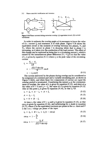
Figure 9.36 Phase currents during converter overlap: (a) equivalent circuit; (b) current
waveforms
In order to estimate the overlap angle p it is necessary to know the value
of d.c. current Id and reactance X in each phase. Figure 9.36 shows the
equivalent circuit at the moment of overlap between two phases, VI and
V2, where the current in phase 1 is decaying whilst that in phase 2 is
increasing, as it takes over the conduction of the load current. The effect of
this change can be explained as being due to a circulating current i, which is
caused by the instantaneous phase difference ( Vl - V2)/2 so that the value
of i, is given by equation (9.1 1) where 1, is the peak value of the circulating
current.
v2 - Vl
i, =
2x
- -- cos e
J(2) V sin dp
X
= -z,cose (9.11)
The current delivered by the phases during overlap can be considered to
be composed of a constant part and a variable circulating part, as shown in
Figure 9.36(b), and when these two components of current are equal the
overlap period is terminated. Considering the instant to at the commence-
ment of overlap, the value of il is given by equation (9.12), and since at
the value of 0 = 0 and ic=-Z,, the value of A is given by equation (9.13).
Also at this point i2 is given by equation (9.14), so that I,=B.
il=Zd=A-ic=A+Z, (9.12)
A = Id - Zc (9.13)
i2 = 0 = B-I, (9.14)
At time tl the value of 8 = CI. and i2 is given by equation (9.15), so that
cos p is given by equation (9.16), and substituting for IC leads to equation
(9.17), where Xis the equivalent reactance per phase in the a.c. lines and V
is the r.m.s. voltage per phase of the input.
i2 = Id = B + i, = Zc(l - cosp) (9.15)
cosp = 1 - - (9.16)
Id
1,
cosp = 1 - Id x (9.17)
42) V sin dp