
Page 219 - Power Electronics Handbook
P. 219
The effect of source reactance 209
zero since the load current free-wheels through devices in the top and
bottom half of the bridge, the effect on the input line voltage being seen to
be such as to introduce further instances of zero voltage.
Overlap in thyristor converters can result in three operating modes as
well, but the Occurrence of mode two, which is so important in diode
circuits, is rare and is often considered as a special case of mode one.
Figure 9.33 gives the waveforms for the bi-directional bridge shown in
Figure 9.11, the delay angle OL being taken as 80" and the overlap angle p as
20''. At time to the red phase becomes the most positive line, but the firing
of thyristor THI is delayed to time When this is done current transfer
occurs between THs and THI, this overlap terminating at toz and thyristor
TH5 going off. Similarly, the commutation between the negative half of the
yellow and blue phases is delayed from fl to tll and so on. The load voltage
is given by the difference between the two instantaneous waveforms, as
before, and is now seen to have negative (regenerative) periods, the line
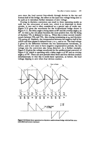
voltage into the converters also being distorted. As a further example,
Figure 9.34 gives the voltage waveforms for the unidirectional converter of
Figure 9.18, which is operating with a delay angle (I[ of 30" and an overlap
angle p of 70". There are now periods when three and four devices conduct
simultaneously so that this is mode-three operation, as before, the load
voltage dipping to zero when four devices conduct.
F@re 9.34 Mode-three operation in a thyristor unidirectional bridge with half the anus
contdkd and source reactance