
Page 223 - Power Electronics Handbook
P. 223
Performance factors 213
- .-
i5
2
-
20
40 -
-
60
80 -
Firing angle (degrees)
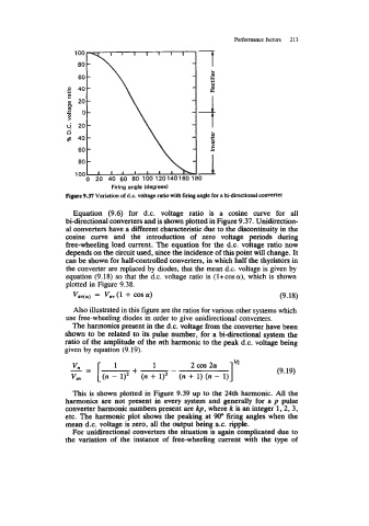
Figure 9.37 Variation of d.c. voltage ratio with firing angk for a bidirectional converter
Equation (9.6) for d.c. voltage ratio is a cosine curve for all
bi-directional converters and is shown plotted in Figure 9.37. Unidirection-
al converters have a different characteristic due to the discontinuity in the
cosine curve and the introduction of zero voltage periods during
bee-wheeling load current. The equation for the d.c. voltage ratio now
depends on the circuit used, since the incidence of this point will change. It
can be shown for halfantrolled converters, in which half the thyristors in
the converter are replaced by diodes, that the mean d.c. voltage is given by
equation (9.18) so that the d.c. voltage ratio is (l+cosa), which is shown
plotted in Figure 9.38.
Vsv(cr) = Vav(1 + co~ar) (9.18)
Also illustrated in this figure are the ratios for various other systems which
use free-wheeling diodes in order to give unidirectional converters.
The harmonics present in the d.c. voltage from the converter have been
shown to be related to its pulse number, for a bi-directional system the
ratio of the amplitude of the nth harmonic to the peak d.c. voltage being
given by equation (9.19).
vll
-= [ l + 1 - 2 cos 2ar I" (9.19)
Vav (n - 1)' (n + I)~ (n + 1) (n - 1)
This is shown plotted in Figure 9.39 up to the 24th harmonic. All the
harmonics are not present in every system and generally for a p pulse
converter harmonic numbers present are kp, where k is an integer 1,2,3,
etc. The harmonic plot shows the peaking at 90" firing angles when the
mean d.c. voltage is zero, all the output being a.c. ripple.
For unidirectional converters the situation is again complicated due to
the variation of the instance of free-wheeling current with the type of