
Page 306 - Power Electronics Handbook
P. 306
296 D.C. link frequency changers
13.2.3.1 Parallel-capacitor commutation
Parallel capacitor commutated circuits are the most popular and the circuit
of Figure 13.11(a) is perhaps one of the earliest used thyristor inverter. In
fact the push-pull inverter is often called a parallel inverter due to the
parallel-capacitor commutation system used, but it will be seen that several
other commutation methods can also be used with push-pull inverters.
The circuit of Figure 13.11(a) is similar to Figure 13.l(a) where the
transistor switches have been replaced by thyristors, inductor L1 is added,
and diodes D1 and D2 have been omitted. Figure 13.11(b) shows a more
efficient system. Firing thyristor TH1 charges capacitor C with plate a
positive, to a voltage of 2vB. When TH2 is turned on capacitor C is
connected across TH1 turning it off. The capacitor now discharges to zero
voltage, its stored energy then being dissipated in the L1-D1-C-THP
conduction path. After this, capacitor C charges to 2vB with plate b
positive, ready to turn TH2 off when THI is fired.
Load
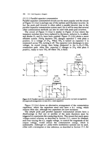
Figwe 13.11 Parallel-capacitor commutation in a push-pull inverter: (a) basic arrangement;
(b) improved arrangement; (c) use of d.c. rated capacitors
Figure 13.11(c) shows an alternative arrangement of the commutation
capacitors, where the capacitors need only have a d.c. rating, which
reduces their size, although two capacitors are now necessary.
The simple push-pull parallel capacitor commutated circuits have a
disadvantage in that one or another of the main thyristors must be
triggered to commutate the conducting device. This means that mark-space
voltage-control schemes, as described in Section 13.3, cannot be obtained,
and even varying the d.c. supply voltage, to control the magnitude of the
output voltage, would reduce the commutation energy, which is
undesirable. Although h.f. pulse-width modulation systems can be used,
either with a rectangular or sine reference, as described in Section 13.3, the