
Page 309 - Power Electronics Handbook
P. 309
Inverter circuits 299
capacitor C is charged to voltage V, with plate a positive. Firing TH8 will
cause the capacitor to resonate through L and recharge with plate b
positive, the voltage being increased if auxiliary supply VBl is included.
When TH7 is next fired capacitor C short-circuits the input to the bridge
inverter and causes all the conducting thyristors in both arms of the bridge
to turn off. It is important once again to bear in mind that turning off all
devices will not make the load voltage zero. This can only be obtained by
refiring appropriate devices to allow the current to free-wheel through
them.
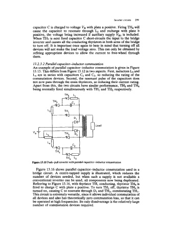
13.2.3.2 Parallel capacitor-inductor commutation
An example of parallel capacitor-inductor commutation is given in Figure
13.15. This differs from Figure 13.12 in two aspects. First, inductors and
L4 are in series with capacitors C1 and G, so reducing the rating of the
commutation devices. Second, the resonant pulse of the capacitors does
not now pass through the main thyristors, so reducing their current rating.
Apart from this, the two circuits have similar performance, TH5 and 'I?&
being normally fired simultaneously with THl and TH2 respectively.
"B
TH, Lz
F+ 13.15 Push-pull inverter with parallel capacitor-inductor commutation
Figure 13.16 shows parallel capacitor-inductor commutation used in a
bridge circuit. A centre-tapped supply is illustrated, which reduces the
number of devices needed, but when such a supply is not available a
conventional inverter can be used, all components now being duplicated.
Referring to Figure 13.16, with thyristor TH1 conducting, thyristor TH, is
fired to charge C with plate a positive. To turn TH1 off, thyristor TH3 is
turned on, causing C to resonate through D1 and TH3, commutating THl.
This circuit is extremely versatile, since it allows individual commutation of
all devices and also has theoretically zero commutation loss, so that it can
be operated at high frequencies. Its only disadvantage is the relatively large
number of commutation devices required.