
Page 312 - Power Electronics Handbook
P. 312
302 D.C. link frequency changers
t
Three phase load
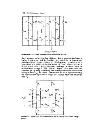
Figure 13.20 Coupled-pulse commutated three-phase bridge inverter
does, however, suffer from low efficiency, due to commutation losses at
higher frequencies, and is therefore not suited for voltage-control
techniques which require an inherent high-frequency operation, such as
pulse-width modulation described in Section 13.3. Also it cannot be used in
circuits which use d.c. supply variations to change the output, since the
commutation voltage is now affected. Figure 13.21 overcomes this
disadvantage by using an auxiliary fixed-voltage low-power commutation
voltage source Vsl, the diodes in series with the main thyristor enabling
the commutation capacitors to charge to a voltage which can be greater
than VB.
"E
3
Figure 13.21 Coupled-pulse commutated inverter with an auxiliary commutation voltage
source