
Page 315 - Power Electronics Handbook
P. 315
Inverter circuits 305
The operating frequency of the inverter of Figure 13.23 is limited by the
requirement af ensuring that devices are reverse biased for longer than
their turn-off time. Figure 13.24 shows a three-stage sequential inverter
which overcomes this limitation, its operation being essentially as for a
sequential chopper introduced in Chapter 12, the thyristor conducting
periods being indicated in Figure 13.24(c).
It has been seen that series-commutated inverters are most efficient
when used with sine wave converters in which the inverter frequency is
related to the resonant load frequency. In discussions so far the two
frequencies have been maintained equal, but this does not necessarily have
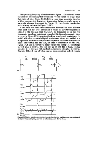
to be so. In Figure 13.25 the output load is a tuned circuit consisting of
and C, which has a relatively high Q, so that once it is set into oscillation it
will produce a sine wave output whose amplitude decreases slowly due to
losses. Periodically THI and TH2 are fired to compensate for this loss.
Figure 13.25 also shows various circuit waveforms. Firing THI will charge
C1 with plate a positive. TI31 will now go off and THz is fired, causing
capacitor C1 to resonate with the load and recharge with plate b positive.
Thyristor TH2 will turn-off when this has been completed and will remain
volts .+-J-- & -
TH,
1
) volts . I I I I I I I
I
I I
I I I
I I
current I I
I I I
Cl
volts
I I I
I I
THZ I I
current 1 I
I I I
Cz-Lz
volts
(b, Firing
pulses -
Figure 13.25 Series capacitor commutatcd inverter in which the load frequency is a multiple of
the thyristor operating frequency: (a) circuit arrangement; (b) waveforms