
Page 320 - Power Electronics Handbook
P. 320
3 10 D.C. link frequency changers
,,c
-- II
+ VB TH1 T"2
4 2z 425
L,
-
13.31 Push-pull inverter with series inductor voltage boost
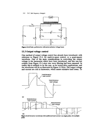
13.3 Output voltage control
One method of output voltage control has already been introduced, with
reference to Figure 13.4, for mark-to-space control, or a quasi-square
waveform. One of the main considerations in controlling the output
voltage is the harmonics which have been introduced, and this was not
evident from Figure 13.4 since sine wave filtering had been assumed. In
reality this is unlikely to be the case, as for motor-drive applications, and
the waveforms will be as illustrated in Figure 13.32(a). The output voltage
and current are rich in harmonics, which causes excessive load losses. To
n ln-+antaneous
d current
instantaneous
lnad vnltana
Instantaneous
load current \
13.32 Inverter waveforms with untiltered load Current: (a) single puk; (b) multiple
P*