
Page 325 - Power Electronics Handbook
P. 325
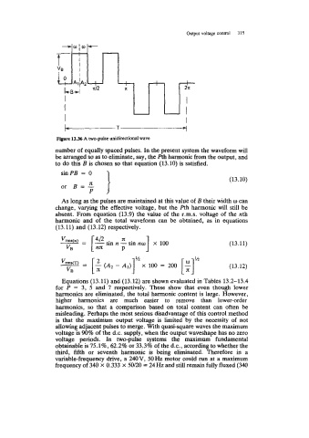
Output voltage control   315

                         li
                      -w[w-
                    t-i
                           I
                    VI3
                           I
                      0
                                           I         I         I
                                           I  *      1  -      I
                       I                                       I
                       I                                - 1


                                                                              (13.11)
                       VB        nn       P


                                                                              (13.12)

                      Equations (13.11) and (13.12) are shown evaluated in Tables 13.2-13.4
                    for  P  = 3,  5  and  7  respectively.  These  show  that  even  though  lower
                    harmonics are eliminated, the total harmonic content is large. However,
                    higher  harmonics  are  much  easier  to  remove  than  lower-order
                    harmonics,  so  that  a  comparison  based  on  total  content  can  often  be
                    misleading. Perhaps the most serious disadvantage of this control method
                    is  that  the  maximum  output  voltage  is  limited  by  the  necessity of  not
                    allowing adjacent pulses to merge. With quasi-square waves the maximum
                   voltage is 90% of  the d.c. supply, when the output waveshape has no zero
                   voltage  periods.  In  two-pulse  systems  the  maximum  fundamental
                   obtainable is 75.1%, 62.2% or 33.3% of  the d.c., according to whether the
                    third,  fifth  or  seventh  harmonic  is  being  eliminated.  Therefore  in  a
                   variable-frequency drive, a 240 V, 50 Hz motor could run at a maximum
                   frequency of 340 X 0.333 x 50/20 = 24Hz and still remain fully fluxed (340