
Page 321 - Power Electronics Handbook
P. 321
Output voltage control 3 11
reduce the harmonic content of the load voltage and current. alternative
control techniques can be used, one such system being shown in Figure
13.32(b). The load voltage is made up of several sections of varying
duration, each block switching between zero and the d.c. supply voltage.
The placing and width of these periods are such as to give a mean a.c.
voltage which approximates closely to a sine wave, the load current being
seen to have a smaller low-frequency harmonic content than that in the
traditional voltage-control system of Figure 13.32(a).
This section describes the various voltage-control techniques which can
be used for inverter circuits, and the impact which these have on the output
harmonics. Voltage control within an inverter is usually required for two
applications :
(i) When the output is to be kept at a fixed value, compensating for
regulation effects within the inverter, or for fluctuations in the supply
voltage or the load current. These requirements usually arise in
fixed-frequency inverter supplies.
(ii) When the output is to be varied in a given manner, for example
proportional to the frequency to keep the flux within the load
constant, such as required for variable-frequency motor drives.
There are several ways in which this voltage control can be achieved, in
all these cases the a.c. being composed of a fundamental component and a
band of harmonic frequencies. The various control methods all contrive to
reduce the harmonic voltages whilst avoiding excessive circuit complexity.
In this section these techniques are classified as unidirectional switching,
bi-directional switching, and waveform synthesis.
I i
- - T -
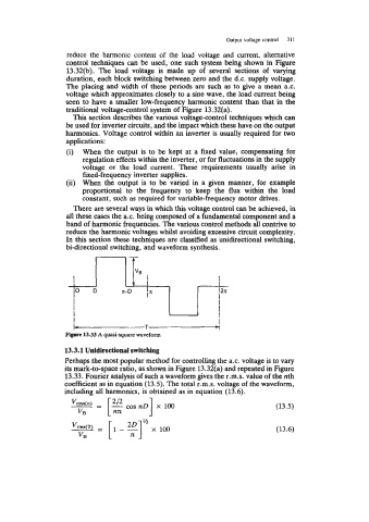
Figure 13.33 A quasi-square waveform
13.3.1 Unidirectional switching
Perhaps the most popular method for controlling the a.c. voltage is to vary
its mark-to-space ratio, as shown in Figure 13.32(a) and repeated in Figure
13.33. Fourier analysis of such a waveform gives the r.m.s. value of the nth
coefficient as in equation (13.5). The total r.m.s. voltage of the waveform,
including all harmonics, is obtained as in equation (13.6).
(13.5)
(13.6)