
Page 319 - Power Electronics Handbook
P. 319
Inverter circuits 309
-e - TH3a TH5,
v,
w ,, C
THla
I
1 - 1
TH4gi 04 TH6 D4
1 1
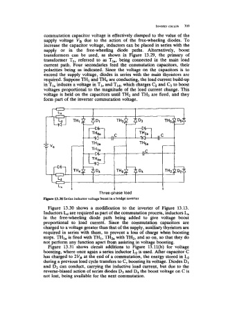
Figure 13.30 shows a modification to the inverter of Figure 13.13.
Inductors Ld are required as part of the commutation process, inductors L,
in the free-wheeling diode path being added to give voltage boost
proportional to load current. Since the commutation capacitors are
charged to a voltage greater than that of the supply, auxiliary thyristors are
required in series with them, to prevent a loss of charge when boosting
stops. TH1, is fired with TH1, THh with TH2, and so on, so that they do
not perform any function apart from assisting in voltage boosting.
Figure 13.31 shows circuit additions to Figure 13.11(b) for voltage
boosting, where once again a series inductor is used. After capacitor C
has charged to 2V* at the end of a commutation, the energy stored in
during a previous load cycle transfers to C, boosting its voltage. Diodes D1
and D2 can conduct, carrying the inductive load current, but due to the
reverse-biased action of series diodes D3 and D4 the boost voltage on C is
not lost, being available for the next commutation.