
Page 314 - Power Electronics Handbook
P. 314
304 D.C. link frequency changers
capacitor through the load, so that for low-loss circuits the reset time is
considerably reduced.
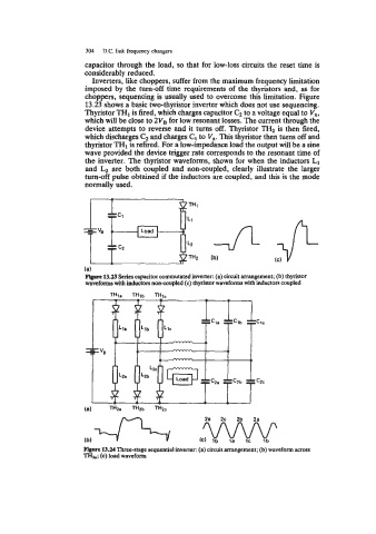
Inverters, like choppers, suffer from the maximum frequency limitation
imposed by the turn-off time requirements of the thyristors and, as for
choppers, sequencing is usually used to overcome this limitation. Figure
13.23 shows a basic two-thyristor inverter which does not use sequencing.
Thyristor TH1 is fired, which charges capacitor C, to a voltage equal to V,,
which will be close to 2VB for low resonant losses. The current through the
device attempts to reverse and it turns off. Thyristor TH2 is then fired,
which discharges C, and charges C1 to V,. This thyristor then turns off and
thyristor THI is refired. For a low-impedance load the output will be a sine
wave provided the device trigger rate corresponds to the resonant time of
the inverter. The thyristor waveforms, shown for when the inductors L1
and are both coupled and non-coupled, clearly illustrate the larger
turn-off pulse obtained if the inductors are coupled, and this is the mode
normally used.
(c) v
U L2
13.23 Series capacitor commutated inverter: (a) circuit arrangement; (b) thyristor
waveforms with inductors non-coupled (c) thyristor waveforms with inductors coupled
Figure 13.24 Three-stage sequential inverter: (a) circuit arrangement; (b) waveform across
TH-; (c) load waveform