
Page 316 - Power Electronics Handbook
P. 316
306 D.C. link frequency changers
reverse biased so long as the peak amplitude of the load oscillations is
arranged to be lower than the capacitor voltage, as shown clearly by the
circuit waveforms. Such an inverter is very useful, since the output
frequency can be several times the inverter frequency, enabling slower
turn-off thyristors to be used, although if the Q of the load circuit is low,
the inverter frequency approaches the output frequency and in the limit
must be equal to it.
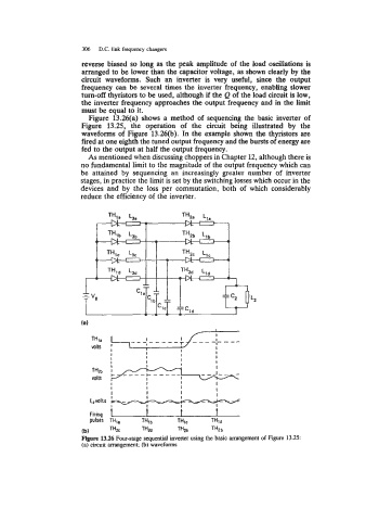
Figure 13.26(a) shows a method of sequencing the basic inverter of
Figure 13.25, the operation of the circuit being illustrated by the
waveforms of Figure 13.26(b). In the example shown the thyristors are
fired at one eighth the tuned output frequency and the bursts of energy are
fed to the output at half the output frequency.
As mentioned when discussing choppers in Chapter 12, although there is
no fundamental limit to the magnitude of the output frequency which can
be attained by sequencing an increasingly greater number of inverter
stages, in practice the limit is set by the switching losses which occur in the
devices and by the loss per cornmutation, both of which considerably
reduce the efficiency of the inverter.
t I I I
I I I I I I I I
-
-
Firing fi
I
I
-
- -
L#VOltS
pulses TH,, THlb THlC THld
(b) T", T"2e THZa THZb
Figure 13.26 Four-stage sequential inverter using the basic arrangement of Figure 13.25:
(a) circuit arrangement; (b) waveforms