
Page 311 - Power Electronics Handbook
P. 311
I
Inverter circuits
301
OL
OL
TH,
TH,
T ", TH, TH, Load
I OL
I 1
- Load current
t
- Load voltage
t
- Thyristor current
t
c Thyristor voltage
, Ill1 I t
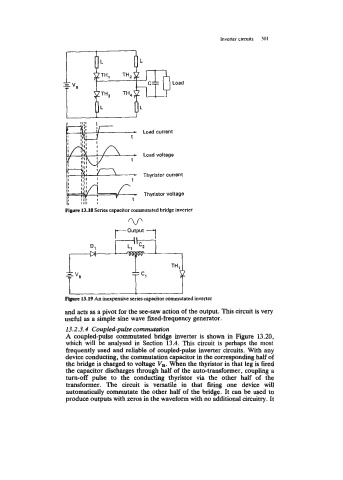
Fi~ure 13.18 Series capacitor commutated bridge inverter
Figure 13.19 An inexpensive series capacitor commutated inverter
and acts as a pivot for the see-saw action of the output. This circuit is very
useful as a simple sine wave fixed-frequency generator.
13.2.3.4 Coupled-puke commutation
A coupled-pulse commutated bridge inverter is shown in Figure 13.20,
which will be analysed in Section 13.4. This circuit is perhaps the most
frequently used and reliable of coupled-pulse inverter circuits. With any
device conducting, the commutation capacitor in the corresponding half of
the bridge is charged to voltage V,. When the thyristor in that leg is fired
the capacitor discharges through half of the auto-transformer, coupling a
turn-off pulse to the conducting thyristor via the other half of the
transformer. The circuit is versatile in that firing one device will
automatidy commutate the other half of the bridge. It can be used to
produce outputs with zeros in the waveform with no additional circuitry. It