
Page 330 - Power Electronics Handbook
P. 330
320 D.C. link frequency changers
45 m
-
40
-
35
30 -
J
0
.I-
o 25-
s?
In
m
0 .-
= 20-
E
z
c
E 15 -
(Ji
2 10 -
“0 20 40 60 80 100
R.M.S. fundamental as % of d.c.
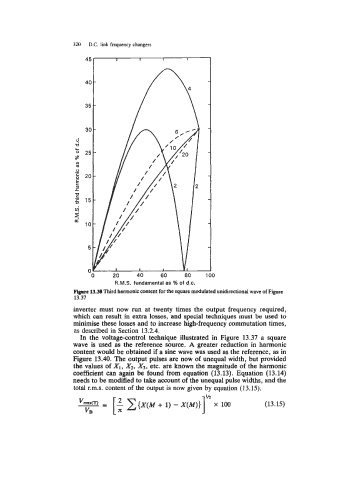
Figure 13.38 Third harmonic content for the square modulated unidirectional wave of Figure
13.37
inverter must now run at twenty times the output frequency required,
which can result in extra losses, and special techniques must be used to
minimise these losses and to increase high-frequency commutation times,
as described in Section 13.2.4.
In the voltage-control technique illustrated in Figure 13.37 a square
wave is used as the reference source. A greater reduction in harmonic
content would be obtained if a sine wave was used as the reference, as in
Figure 13.40. The output pulses are now of unequal width, but provided
the values of XI, X2, X3, etc. are known the magnitude of the harmonic
coefficient can again be found from equation (13.13). Equation (13.14)
needs to be modified to take account of the unequal pulse widths, and the
total r.m.s. content of the output is now given by equation (13.15).
VB [IC I” x 100 (13.15)
{X(M + 1) - X(M)}