
Page 329 - Power Electronics Handbook
P. 329
Output voltage control 3 19
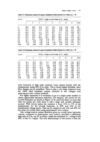
Table 13.7 Harmomic content of a square modulated unidirectiod wave WithfTlfS = 10
~ ~~
R. M.S. voltage as percentage of d.c. supply
1 3 5 7 9 11 13 15 Total
0 90.0 30.0 18.0 12.9 10.0 8.16 6.94 6.00 100
0.1 81.3 27.8 17.8 14.6 18.2 0.85 4.37 5.33 94.9
0.2 72.4 25.4 17.1 15.6 25.0 9.77 1.09 3.51 89.4
0.3 63.6 22.7 16.1 15.9 29.7 17.5 2.37 0.92 83.7
0.4 54.6 19.9 14.6 15.4 32.1 23.2 5.44 1.87 77.5
0.5 45.6 16.8 12.7 14.1 32.0 26.2 7.61 4.26 70.7
0.6 36.5 13.6 10.6 12.2 29.3 26.0 8.52 5.72 63.2
0.7 27.4 10.3 8.19 9.72 24.3 22.8 8.03 5.94 54.8
0.8 18.3 6.93 5.58 6.75 17.4 16.9 6.22 4.87 44.7
0.9 9.17 3.47 2.83 3.45 9.05 8.99 3.38 2.74 31.6
0.98 1.85 0.68 0.58 0.68 1.85 1.85 0.68 0.58 14.1
As/& R. M.S. voitage os percentage of d.c. supply
1 3 5 7 9 11 13 15 Total
0.1 81.1 27.2 16.5 12.1 9.68 8.28 7.49 7.23 94.9
0.2 72.1 24.3 15.0 11.1 9.16 8.14 7.75 8.07 89.4
0.3 63.1 21.4 13.3 10.0 8.46 7.15 7.69 8.46 83.7
0.4 54.1 18.4 11.6 8.84 7.59 7.13 7.31 8.38 77.5
0.5 45.1 15.4 9.14 7.54 6.58 6.30 6.62 7.84 70.7
0.6 36.1 12.4 7.87 6.14 5.42 5.28 5.66 6.86 63.2
0.7 27.1 9.31 5.94 4.67 4.17 4.10 4.47 5.51 54.8
0.8 18.1 6.22 3.98 3.15 2.82 2.81 3.09 3.85 44.7
0.9 9.04 3.11 2.00 1.58 1.43 1.42 1.58 1.98 31.6
0.98 1.81 0.62 0.40 0.32 0.29 0.29 0.32 0.40 14.1
third harmonic at high pulse numbers varies almost linearly with the
fundamental, being 30% of its value. This is clearly highly desirable, since
filter designs can be simplified. There is also a very large reduction from
the 100% third harmonic content obtained at low voltages with
quasi-square wave control methods.
For higher harmonics it is necessary to go to a larger pulse number to
obtain appreciable harmonic reduction. For instance, the curves for the
seventh harmonic are shown in Figure 13.39, and from these it is seen that
with ten pulses per cycle there is still a large and variable harmonic
content. With twenty pulses the variation is from 14% to 17% of the
fundamental, for the seventh harmonic, at 90% and 10% of the
fundamental voltage points. This can be compared with 14% and 90% for
the same two points when using quasi-square wave control.
This voltage-control system therefore gives an overall lower harmonic
content, compared to quasi-square wave control, provided a sufficiently
high ratio off&, say 20, is chosen, whilst the maximum d.c. voltage is still
90% of the d.c. supply. The only disadvantage of this system is that the