
Page 327 - Power Electronics Handbook
P. 327
Output voltage control 3 17
Table 13.4 Harmonics in a two-pulse unidirectional wavt with P = 7
2dT R. M.S. voltage as percentage of d.c. supply
1 3 5 7 9 11 13 15 Total
0.14 33.3 56.7 22.8 0.00 11.4 15.8 3.22 1.61 74.8
0.13 31.0 55.0 25.1 0.00 7.96 15.6 4.97 0.81 72.1
0.12 28.8 52.9 26.8 0.00 3.89 13.5 5.90 3.06 69.3
0.11 26.5 50.3 27.8 0.00 0.49 9.78 5.86 4.64 66.3
0.10 24.1 47.3 28.1 0.00 4.83 4.93 4.86 5.21 63.2
0.09 21.8 43.9 27.8 0.00 8.79 0.50 3.06 4.64 60.0
0.08 19.4 40.0 26.8 0.00 12.0 5.87 0.75 3.06 56.6
0.07 17.0 35.9 25.1 0.00 14.4 10.6 1.68 0.81 52.9
0.06 14.6 31.3 22.8 0.00 15.5 14.0 3.83 1.61 49.0
0.05 12.2 26.6 19.9 0.00 15.4 15.8 5.35 3.68 44.7
0.04 9.79 21.5 16.5 0.00 14.1 15.7 6.00 4.95 40.0
0.03 7.35 16.3 12.8 0.00 11.7 13.7 5.65 5.14 34.6
0.02 4.90 11.0 8.90 0.00 8.38 10.2 4.38 4.21 28.3
0.01 2.45 5.50 4.40 0.00 4.36 5.40 2.39 2.36 20.0
0.00 0.00 0.00 0.00 0.00 0.00 0.00 0.00 0.00 0.00
= 240 x V2, i.e. the peak rectified mains voltage) when the seventh
harmonic is being eliminated.
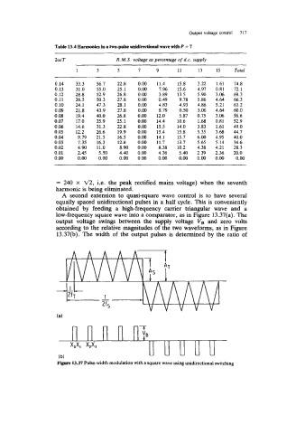
A second extension to quasi-square wave control is to have several
equally spaced unidirectional pulses in a half cycle. This is conveniently
obtained by feeding a high-frequency carrier triangular wave and a
low-frequency square wave into a comparator, as in Figure 13.37(a). The
output voltage swings between the supply voltage V, and zero volts
according to the relative magnitudes of the two waveforms, as in Figure
13.37(b). The width of the output pulses is determined by the ratio of
Figure 13.37 Pulse-width modulation with a square wave using unidirectional switching