
Page 110 - Power Electronics Handbook
P. 110
Circuit design for EMC 103
(b)
s,
-0
L1
(C)
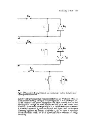
Figure 4.3 Suppression of voltage transients across an inductive load: (a) diode; (b) zener;
(c) voltagedependent resistor
circuit board operating at high frequencies (Butcher and Whithnall, 1993). In
these instances earthing strategies become important, as shown in Figure 4.4.
In the common earth return arrangement the return current from all the
devices passes through the return track to the earth point. The current from
elements 2 and 3 causes a voltage drop of V to appear at the input to element
1 , due to the impedance Zp of the return traci. This signal forms an unwanted
interfering signal at the terminal of element 1, and its effect is especially
severe if elements 2 and 3 are heavy-current devices or element 1 has a high
sensitivity.