
Page 181 - Power Electronics Handbook
P. 181
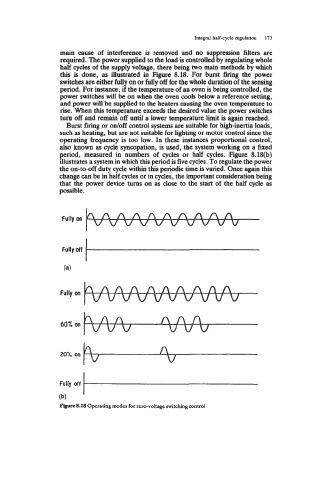
Integral half-cycle regulation   173

                   main  cause  of  interference  is  removed  and  no  suppression filters are
                   required. The power supplied to the load is controlled by regulating whole
                   half cycles of the supply voltage, there being two main methods by which
                   this  is  done,  as illustrated in  Figure  8.18.  For  burst  firing the  power
                   switches are either fully on or fully off for the whole duration of the sensing
                   period. For instance, if the temperature of  an oven is being controlled, the
                   power switches will be on when the oven cools below a reference setting,
                   and power will be supplied to the heaters causing the oven temperature to
                   rise. When this temperature exceeds the desired value the power switches
                   turn off and remain off until a lower temperature limit is again reached.
                     Burst firing or odoff control systems are suitable for high-inertia loads,
                   such as heating, but are not suitable for lighting or motor control since the
                   operating frequency is too low.  In these instances proportional control,
                   also known as cycle syncopation, is used, the system working on a fixed
                   period,  measured  in  numbers  of  cycles  or  half  cycles.  Figure  8.18(b)
                   illustrates a system in which this period is five cycles. To regulate the power
                   the on-to-off duty cycle within this periodic time is varied. Once again this
                   change can be in half cycles or in cycles, the important consideration being
                   that the power device turns on as close to the start of  the half  cycle as
                   possible.


                   60% on


                   Fully  off
                   (b)
                   Figure 8.18 Operating modes for zero-voltage switching control