
Page 179 - Power Electronics Handbook
P. 179
A.C. chopper regulation 171
The gate turn-off switch and transistor are ideally suited for use in a.c.
chopper regulators, since they can be turned off by control of their gate or
base current. Where the power of a thyristor is required the device needs to
be turned off before the end of a half cycle, Le. it must be forced
commutated. Several circuits may be used, as discussed in Chapter 11,
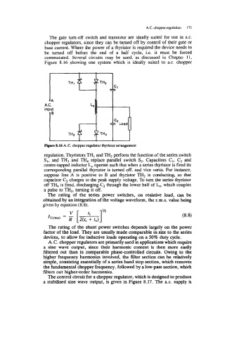
Figure 8.16 showing one system which is ideally suited to a.c. chopper
Flpre 8.16 A.C. chopper regulator thyristor arrangement
regulation. Thyristors TH, and TH2 perfom the function of the series switch
SI, and TH3 and TH4 replace parallel switch S2. Capacitors C1, C2 and
centre-tapped inductor Lo operate such that when a series thyristor is fired its
corresponding parallel thyristor is turned off, and vice versa. For instance,
suppose line A is positive to B and thyristor TH2 is conducting, so that
capacitor C2 charges to the peak supply voltage. To turn the series thyristor
off TH4 is fired, discharging C, through the lower half of Lo, which couples
a pulse to TH2, turning it off.
The rating of the series power switches, on resistive load, can be
obtained by an integration of the voltage waveform, the r.m.s. value being
given by equation (8.8).
The rating of the shunt power switches depends largely on the power
factor of the load. They are usually made comparable in size to the series
devices, to allow for inductive loads operating on a 50% duty cycle.
A.C. chopper regulators are primarily used in applications which require
a sine wave output, since their harmonic content is then more easily
filtered out than in comparable phase-controlled circuits. Owing to the
higher frequency harmonics involved, the filter section can be relatively
simple, consisting essentially of a series band stop section, which removes
the fundamental chopper frequency, followed by a low-pass section, which
filters out higher-order harmonics.
The control circuit for a chopper regulator, which is designed to produce
a stabilised sine wave output, is given in Figure 8.17. The a.c. supply is