
Page 183 - Power Electronics Handbook
P. 183
Synchronous tap changer 175
power semiconductors if required, or operate some other more
continuous drive circuit.
(iii) An amplifier stage which magnifies the control signal to provide the
drive needed to turn the power switches on.
As for phase control there are several integrated circuit devices available
which provide a convenient method for obtaining integral half-cycle
regulation, using both burst and proportional control techniques.
8.5 Synchronous tap changer
In systems which have an output transformer and require only small
adjustment of the voltage, synchronous tap changing is often preferable to
ordinary phase control. Figure 8.20 shows a typical system and its output
waveforms.
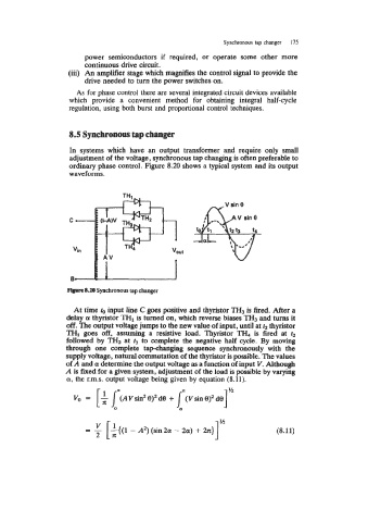
Flgwe 8.20 Synchronous tap changer
At time to input line C goes positive and thyristor TH3 is fired. After a
delay (Y thyristor THl is turned on, which reverse biases TH3 and turns it
off. The output voltage jumps to the new value of input, until at tz thyristor
THl goes off, assuming a resistive load. Thyristor TH4 is fired at fz
followed by TH2 at 4 to complete the negative half cycle. By moving
through one complete tapchanging sequence synchronously with the
supply voltage, natural commutation of the thyristor is possible. The values
of A and a determine the output voltage as a function of input V. Although
A is fixed for a given system, adjustment of the load is possible by varying
a, the r.m.s. output voltage being given by equation (8.11).
P
V, = [$ I, (AVsin20)2d0 +
(8.11)